Disassembling an Anker PowerCore 26800 PD (45W)

The bank only had about a quarter of its power left and refused to begin charging.
One day I went to charge my power bank, an Anker PowerCore 26800. After plugging in the charger and the USB-C cable, I noticed that the charge light no longer came on. No matter what I did, the indicators did not illuminate and the entire thing was dead. I frequently travel with this power bank and like the convenience of having both USB-C and USB A connectors, so throwing it out was the last thing I wanted to do. I wanted to repair it, but because the unit seemed to be sealed with clips, I wasn’t sure how to dissect it and get to the board for a diagnosis. This article details that process, so if you have one, you can tear into yours if necessary.

The scratch is from a camp stove’s sharp leg. The gouge is from the dental tool. Oopsie! Also, note the feet! The Powercore itself slides around quite a bit on a desk or table, so I used Sugru to make some anti-slip feet for it. Sugru is great and every hacker should have some in their toolbox!
The first thing to realize is that there actually are no clips. Instead, the screws are located under a plastic end cap that is adhered to the opposite side of the bank from the connectors. Flipping the Anker around and looking closely reveals a tiny seam between the aluminum body and the plastic cover. Using a fine pick or spudger, it is possible to get between the two. Using some heat and slowly prying should give enough leeway for leverage. I damaged the case a tiny bit because the dental tool dug into the soft aluminum, but I don’t really mind as long as it works.

Don’t worry about the residue. We’ll clean that up in a bit.
Getting under the cap will take some time and patience. Calm down and get a hold of yourself! Eventually you’ll be able to slowly peel the plastic away from the adhesive, although there will be some residue left behind. It will easily clean off with some WD-40 or acetone. There are now four Phillips screws to remove, one in each corner of the bank. Remove these screws, then flip the power supply on its edge and gently shake it like a ketchup bottle. The power supply will slide out of the aluminum sleeve. The power button will fall out. This is perfectly okay and we will put it back in place when we reassembled the pack. Set it aside with the screws and don’t forget about it!

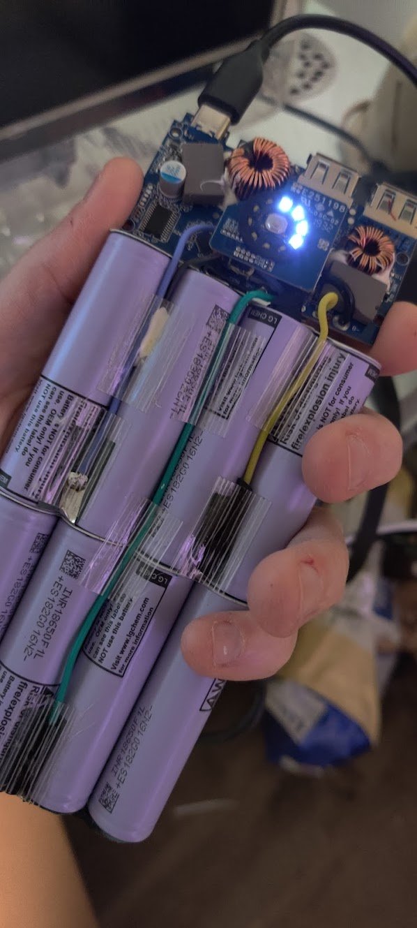
Always a good sign that something isn’t edible. These are LG-branded 18650 cells.
At this point, it’s important to be safe. The logic board of the controller is exposed and could very easily short circuit if it comes into contact with anything metal or any liquids. Use extra caution because of this, and also be careful not to damage the cells that are exposed inside of the bank. They…warn you of…problems…that could occur if something were to puncture these 18650 lithium ion cells, and for good reason, if you’ve never seen one of them explode before.

Careful around the board!
The next step is to remove four screws in the corners of the logic board. You may wish to use a non-conductive screwdriver for this, or disconnect the positive lead coming from the cells before you do this. Avoid making contact with the inductors! As you remove the screws, take note that these are different from the outer chassis ones, so you’ll want to keep them separate, but they’re very different, so confusing the two is pretty unlikely. They are tiny, however, so you may wish to keep them in a safe place. After these screws are removed, the board can be lifted up and turned over, or the entire assembly can be carefully removed from the case.
Probably don’t do this.
The problem in my case was very clear—after heavy use, the USB 3.0 port’s solder had broken free of the board and it was no longer making contact with the pads, which had peeled up from the board. After desoldering the positive connection from the cells and taping the wire back, I gently cleaned everything with 99% isopropyl alcohol, reattached the USB connector to the board, and repaired one trace that had broken. While I was soldering, I had to use a jeweler’s loupe and a fine tip on the Weller, but I eventually got it.

Closeup of the logic board.
Chances were that the power bank was fixed, although the port itself was slightly dirty. I cleaned it out with compressed air and some DeoxIT. Feeling triumphant and brave, I threw caution to the wind, reattached the cells to the board, and live-tested it. Plugging in the USB-C charger for the Anker, I saw the spinning lights almost right away and the pack began gaining energy.
It worked! The port was sturdy and before I began the reassembly process, I decided to reinforce the connector’s housing attachment points with a little more solder. After double-checking my work, I began reassembly.

You can try this, but if it doesn’t work, try using a pair of tweezers or needle-nose pliers to put the button back in the case before putting the pack inside.
The next part is a little tricky, but not overly so. The power button has to be put back into the aluminum shell in the right orientation so the back can slide overtop of it. If the button is not properly aligned, it will not depress correctly once the reassembly happens. Also, when putting things back together, it’s best to ensure that the button is “clicky” before completely inserting the pack into the housing.

The notched corners face outward on the pack like so. If you have it the other way around, turn it or the button may jam inside of the aluminum case.
Place the cells and the logic board back in the plastic tray and use the four attachment screws to secure the logic board at the top of the pack. Once again, be careful of the inductors and exposed parts of the board! It’s very easy to short things out here, and if you’re using metal tools, it becomes very easy to damage something.

Once the board and lithium ion cells are in the tray, the fun part begins. Take a pair of needle-nose pliers or long tweezers and place the button into the case from the inside. You may need to take a couple of tries to get this, and light will help. You may also try placing the button on top of the pack in the correct orientation and sliding it forward, but this can cause the pack to jam if not done correctly. Note that the notches on the button face outward, away from the pack, and not inward. now, carefully slide the pack back into the case. As the bank slides back together, using excessive force can cause the plastic and aluminum to bind and the tray will get stuck. Start over and try again. Eventually, the case will come back together. Check to make sure that the power button is still “clicky” and isn’t getting hung up on the housing. If it is, redo this step. Eventually, everything will come back together. Fasten the case together with the four screws left and try the power bank! if everything works correctly, use some double-sided tape to reaffix the end cap. Don’t use anything like hot glue or epoxy if battery replacement sounds like something for a future project, otherwise the pack will be difficult to disassemble the next time.
That’s it! The power bank works again, and I can keep using it on my camping adventures! In the future, I can now take it apart and replace the lithium ion cells if I need to, and hopefully, this Anker powerCore will last me many more years.